the reason
The reason why I started making receivers is a germanium receiver at home. My grandfather gave it to me when I was little, but I did not know how to use it. I got interested in the system and it led me to make my first self made receiver.
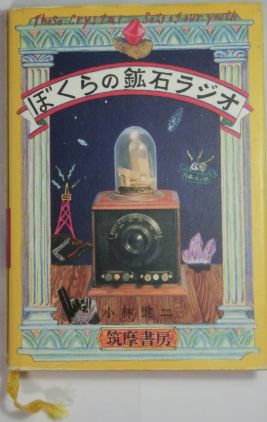
I have a good book whose title is "Those Crystal Sets of our youth". The book is out of print, but I found it at the library. Reading this book, I made the receivers, especially germanium ones. It explains the principle of receivers, functions of coils and capacitors, and techniques of the work widely. It was really helpful for me.
AM #1
August 2019
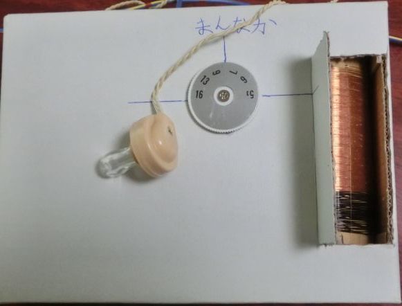
This is a germanium receiver without amplification. I tried to solder for the first time. Solder was too much or too little, and heating was not well. At first it was difficult for me, but I got used to soldering while trying more.
Finished! I thought so, but I could not receive anything. I tried one thing or another, like grounding, only to fail. I googled information that using a loop antenna worked very well. Reading the article, I made a loop antenna, with copper wire winded around a foamed styrol box for forty turns. Then I connected it to the antenna terminal, and I received! That was really small sound, but I was able to receive one station. It was probably NHK Tokyo Radio 2. My first electronic work was successful this way.
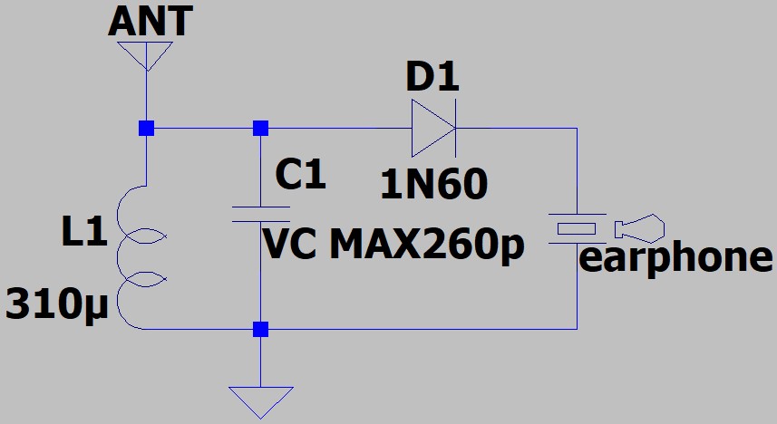
The circuit diagram. Click to enlarge.
AM #2
September 2019
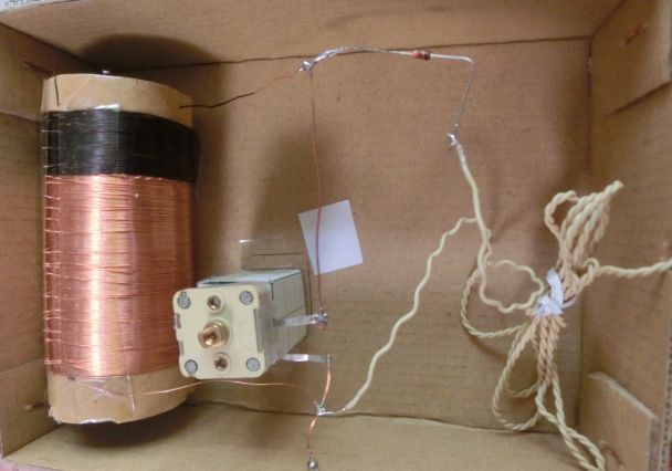
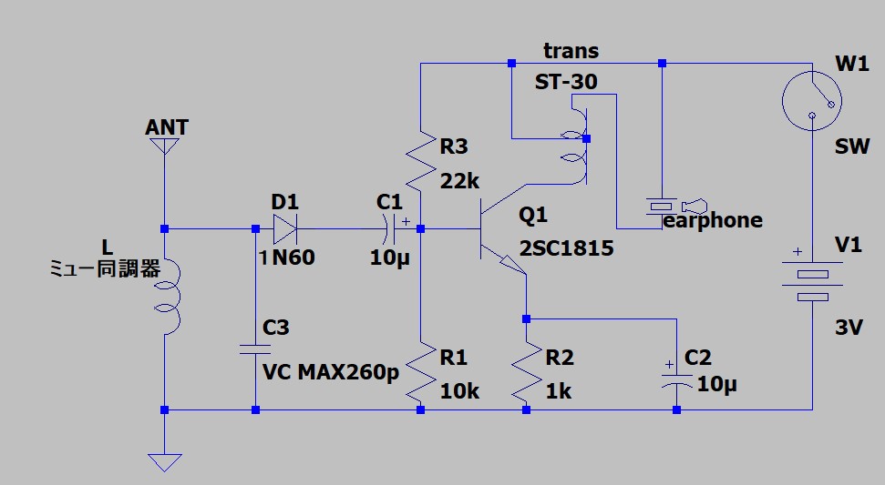
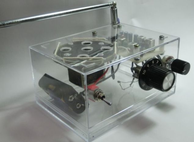
The receiver 2 was a basic germanium receiver same as the first one, but equipped with one transistor of amplification aiming to gain the volume. The "lithos" I used was 2SC1815-Y(TOSHIBA). "Lithos" is a jargon for transistor in Japanese. I also improved the germanium receiver. First, I made a coil which could vary the inductance, because the number of turns of my first self made receiver's coil might be too many or too few, since I knew little about coils. I thought that the receiver would be able to receive wider frequency if I adopted a variable inductor. Then, the one I wished to try was a part so-called μ tuner. But it was not available anywhere, so I tried to make a mimic myself.
It was not very difficult actually, because I needed, in short, only to get the inductance of a coil variable. First, I made a coil, using a broken ball-point pen as a core. Then, I put a ferrite rod in the coil and attached a pinch to push and pull it. That was all.
I winded a spider coil to compare, but my selfmade μ tuner seemed to work better in sensivity and selectivity. I adopted a common emitter low frequency amplifier.
When I use this receiver, I can receive broadcasting, using the loop antenna which I made for my first receiver, or connecting ground wire of power cable of PC to the antenna terminal. I felt that the latter had better sensibility. This receiver became good enough to receive local stations.
I became able to collet verification cards of local stations by making this reveiver. Using this one, I got the cards from Bunka Broadcasting, KBC Radio, and CBC Radio.
The circuit diagram. Click to enlarge.
AM #3
December 2019
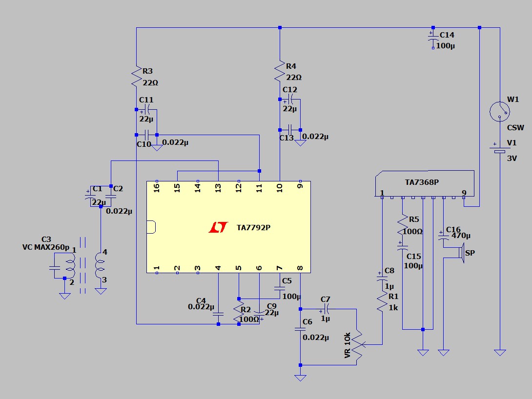
This is a straight receiver using a radio IC. I used TA7792P(TOSHIBA) which was designed for superheterodyne receivers. But I adopted straight system, because I was afraid that I might make a mistake of adjusting superheterodyne as I knew little about it, and maybe I could not get parts like a coil for a local oscillator. And I also used TA7368(TOSHIBA) as an amplifier to gain the volume.
As I checked how the bare circuit worked, I found the volume was awesome big! Its usability was far beyond my previoius receivers. When I put them into the case, it became more stable. I found it was able to receive really far stations during the night. By making this one, I became able to receive far distance AM stations. I collected the cards from ROK Radio, HBC Radio, RCC Broadcasting with this one.
The circuit diagram. Click to enlarge.
FM #1
December 2019
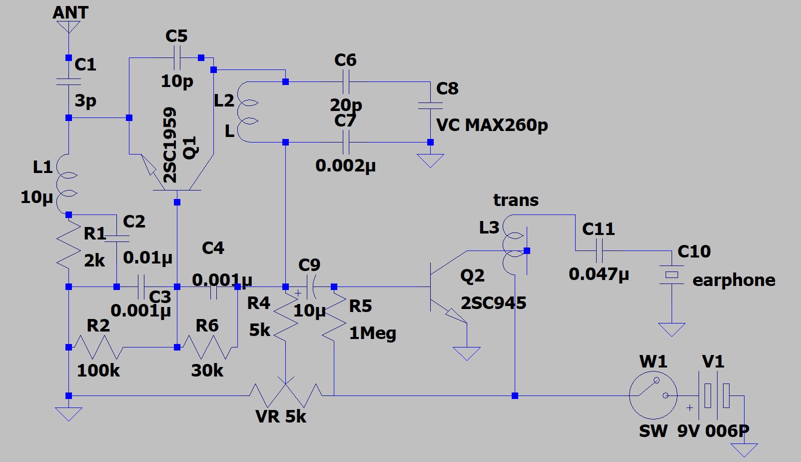
This time, I tried to make my first FM receiver, adopting regenerative detector circuit with 2 transistors. Since variable capacitors of small capacity used for FM receivers were expensive, I tried to connect capacitors in series to a variable capacitor of 260pF designed for AM receivers, in order to down thier capacity.
I checked how the bare circuit worked, but receiving frequency was shifted after I put them into the case, perhaps because human body affected differently. But it was no problem, as the receiving frequency was wide. I'll introduce about tuning of this receiver. First, tuning in the variable resistor to hear the sound. Then, tuning in the variable capacitor to select the station. I tuning slowly or I miss the station, as the capacity of variable capacitor is little big. The tuning is difficult, because I must tuning in the variable capacitor and the variable resistor, but I wont to the tuning and I became able to receive the broadcasting. I collected the cards from Tokyo FM, FM Tokushima, FM Aichi with this one.
The circuit diagram. Click to enlarge.
FM #2
April 2020
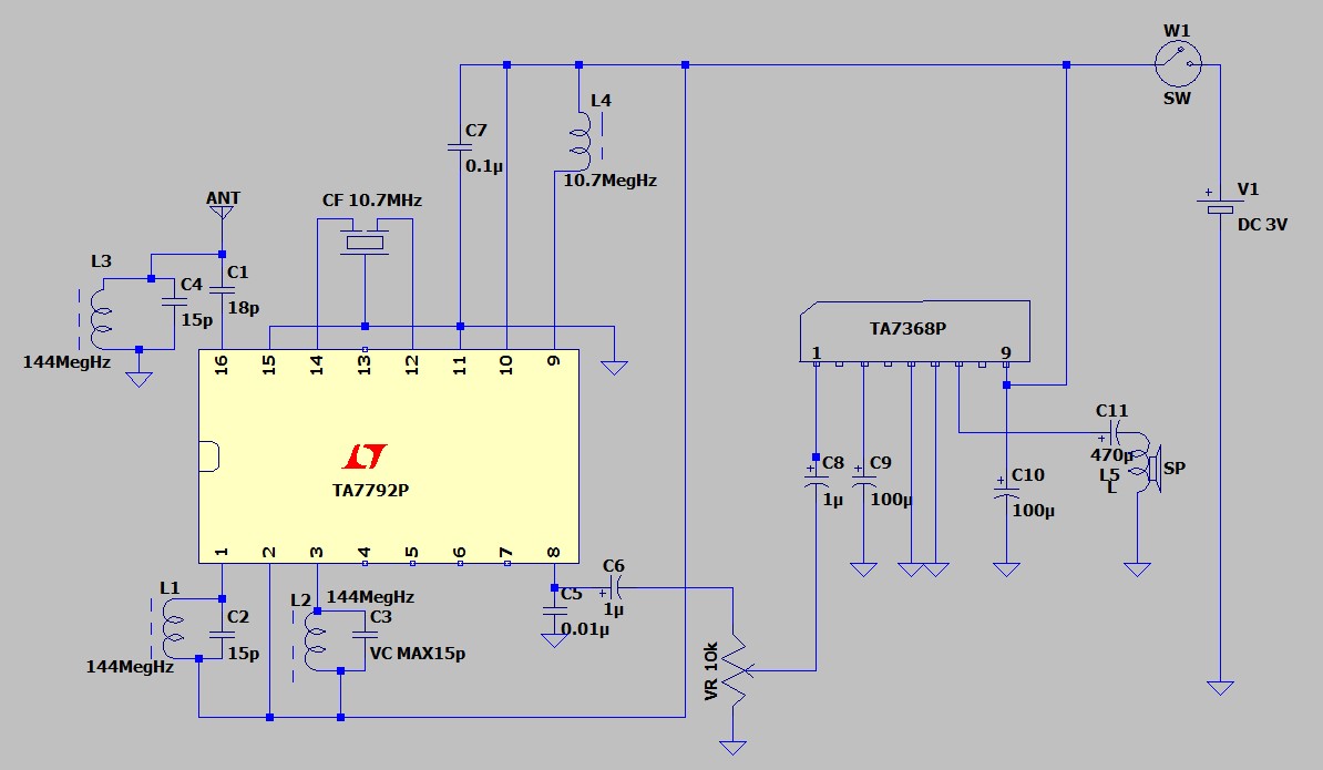
I made this receiver, as I wanted to listen to the FM radio on a speaker. I decided to make superheterodyne receiver using two ICs, TA7792P(TOSHIBA) and TA7368(TOSHIBA) which I used for AM receiver #3.
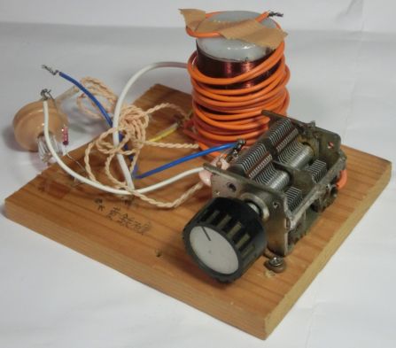
First of all, I checked the operation on a temporary wired breadboard. I connected terminals of a variable condenser to the breadboard with alligator clips at first, but I could not hear anything, as the alligator clips were too long. Then I shortened the wiring, and the set became able to receive broadasting. The higher frequency is, the better shorter wiring is, I guess. Well done. The receiver demodulated very well. But the shaft of variable condenser did not fit my knobs available, because the variable condenser was of inch size made in the U.S. The diameter of the shaft of domestic parts is 6.1mm, but that of the american is 6.35mm. I filed the shaft to fit my knob, not only because it was hard to pinch and turn it with fingers, but also because human body affected significantly.
Then, I mounted the parts on the universal board, but it didn't work. I thought that I must make a mistake of wiring because this set worked on the breadboard. I have investigated many points to find the cause, only to fail. Since it couldn't be helped, I detached the parts from the board once and mounted the parts on the board again carefully. This time, I made it! I was satisfied with the sensitivity and sound quality of this receiver. I collected the cards of FM Hokkaido, FM North Wave using this one.
After that, I improved the sound quality adjusting the core of the coils. And the volume was so big on the first circuit, that I inserted an 80Ω resistor before input #3 pin of TA7368. The operability got better.
I am now studying a converter which can receive 2 meters amateur band using this receiver as a master receiver.
The circuit diagram. Click to enlarge.